Deprecated: Creation of dynamic property escapecode_plugin::$classfile_path is deprecated in /home/u723625802/domains/skillicon.in/public_html/blogs/inc/plugins/model/_plugins.class.php on line 413
Deprecated: Creation of dynamic property tinymce_plugin::$classfile_path is deprecated in /home/u723625802/domains/skillicon.in/public_html/blogs/inc/plugins/model/_plugins.class.php on line 413
Deprecated: Creation of dynamic property wikitables_plugin::$classfile_path is deprecated in /home/u723625802/domains/skillicon.in/public_html/blogs/inc/plugins/model/_plugins.class.php on line 413
Deprecated: Return type of ExplodeIterator::current() should either be compatible with Iterator::current(): mixed, or the #[\ReturnTypeWillChange] attribute should be used to temporarily suppress the notice in /home/u723625802/domains/skillicon.in/public_html/blogs/plugins/wikitables_plugin/_string_utils.inc.php on line 529
Deprecated: Return type of ExplodeIterator::next() should either be compatible with Iterator::next(): void, or the #[\ReturnTypeWillChange] attribute should be used to temporarily suppress the notice in /home/u723625802/domains/skillicon.in/public_html/blogs/plugins/wikitables_plugin/_string_utils.inc.php on line 540
Deprecated: Return type of ExplodeIterator::key() should either be compatible with Iterator::key(): mixed, or the #[\ReturnTypeWillChange] attribute should be used to temporarily suppress the notice in /home/u723625802/domains/skillicon.in/public_html/blogs/plugins/wikitables_plugin/_string_utils.inc.php on line 533
Deprecated: Return type of ExplodeIterator::valid() should either be compatible with Iterator::valid(): bool, or the #[\ReturnTypeWillChange] attribute should be used to temporarily suppress the notice in /home/u723625802/domains/skillicon.in/public_html/blogs/plugins/wikitables_plugin/_string_utils.inc.php on line 558
Deprecated: Return type of ExplodeIterator::rewind() should either be compatible with Iterator::rewind(): void, or the #[\ReturnTypeWillChange] attribute should be used to temporarily suppress the notice in /home/u723625802/domains/skillicon.in/public_html/blogs/plugins/wikitables_plugin/_string_utils.inc.php on line 511
Deprecated: Creation of dynamic property custom_tags_plugin::$classfile_path is deprecated in /home/u723625802/domains/skillicon.in/public_html/blogs/inc/plugins/model/_plugins.class.php on line 413
Deprecated: Creation of dynamic property calendar_plugin::$classfile_path is deprecated in /home/u723625802/domains/skillicon.in/public_html/blogs/inc/plugins/model/_plugins.class.php on line 413
Deprecated: Creation of dynamic property calendar_plugin::$dbtable is deprecated in /home/u723625802/domains/skillicon.in/public_html/blogs/plugins/_calendar.plugin.php on line 53
Deprecated: Creation of dynamic property calendar_plugin::$dbprefix is deprecated in /home/u723625802/domains/skillicon.in/public_html/blogs/plugins/_calendar.plugin.php on line 54
Deprecated: Creation of dynamic property calendar_plugin::$dbIDname is deprecated in /home/u723625802/domains/skillicon.in/public_html/blogs/plugins/_calendar.plugin.php on line 55
Deprecated: Creation of dynamic property markdown_plugin::$classfile_path is deprecated in /home/u723625802/domains/skillicon.in/public_html/blogs/inc/plugins/model/_plugins.class.php on line 413
Deprecated: Creation of dynamic property quicktags_plugin::$classfile_path is deprecated in /home/u723625802/domains/skillicon.in/public_html/blogs/inc/plugins/model/_plugins.class.php on line 413
Deprecated: Creation of dynamic property auto_anchors_plugin::$classfile_path is deprecated in /home/u723625802/domains/skillicon.in/public_html/blogs/inc/plugins/model/_plugins.class.php on line 413
Deprecated: Creation of dynamic property shortlinks_plugin::$classfile_path is deprecated in /home/u723625802/domains/skillicon.in/public_html/blogs/inc/plugins/model/_plugins.class.php on line 413
Deprecated: Creation of dynamic property shortcodes_plugin::$classfile_path is deprecated in /home/u723625802/domains/skillicon.in/public_html/blogs/inc/plugins/model/_plugins.class.php on line 413
Deprecated: Creation of dynamic property archives_plugin::$classfile_path is deprecated in /home/u723625802/domains/skillicon.in/public_html/blogs/inc/plugins/model/_plugins.class.php on line 413
Deprecated: Creation of dynamic property archives_plugin::$dbtable is deprecated in /home/u723625802/domains/skillicon.in/public_html/blogs/plugins/_archives.plugin.php on line 54
Deprecated: Creation of dynamic property archives_plugin::$dbprefix is deprecated in /home/u723625802/domains/skillicon.in/public_html/blogs/plugins/_archives.plugin.php on line 55
Deprecated: Creation of dynamic property archives_plugin::$dbIDname is deprecated in /home/u723625802/domains/skillicon.in/public_html/blogs/plugins/_archives.plugin.php on line 56
Deprecated: Creation of dynamic property email_elements_plugin::$classfile_path is deprecated in /home/u723625802/domains/skillicon.in/public_html/blogs/inc/plugins/model/_plugins.class.php on line 413
Deprecated: Creation of dynamic property financial_contribution_plugin::$classfile_path is deprecated in /home/u723625802/domains/skillicon.in/public_html/blogs/inc/plugins/model/_plugins.class.php on line 413
Deprecated: Creation of dynamic property inlines_plugin::$classfile_path is deprecated in /home/u723625802/domains/skillicon.in/public_html/blogs/inc/plugins/model/_plugins.class.php on line 413
Deprecated: Creation of dynamic property ping_b2evonet_plugin::$classfile_path is deprecated in /home/u723625802/domains/skillicon.in/public_html/blogs/inc/plugins/model/_plugins.class.php on line 413
Deprecated: Creation of dynamic property ping_pingomatic_plugin::$classfile_path is deprecated in /home/u723625802/domains/skillicon.in/public_html/blogs/inc/plugins/model/_plugins.class.php on line 413
Deprecated: Creation of dynamic property twitter_plugin::$classfile_path is deprecated in /home/u723625802/domains/skillicon.in/public_html/blogs/inc/plugins/model/_plugins.class.php on line 413
Deprecated: Creation of dynamic property webmention_plugin::$classfile_path is deprecated in /home/u723625802/domains/skillicon.in/public_html/blogs/inc/plugins/model/_plugins.class.php on line 413
Deprecated: Creation of dynamic property webmention_plugin::$ping_service_process_message is deprecated in /home/u723625802/domains/skillicon.in/public_html/blogs/plugins/webmention_plugin/_webmention.plugin.php on line 52
Deprecated: Creation of dynamic property webmention_plugin::$ping_service_setting_title is deprecated in /home/u723625802/domains/skillicon.in/public_html/blogs/plugins/webmention_plugin/_webmention.plugin.php on line 53
Deprecated: Creation of dynamic property basic_antispam_plugin::$classfile_path is deprecated in /home/u723625802/domains/skillicon.in/public_html/blogs/inc/plugins/model/_plugins.class.php on line 413
Deprecated: Creation of dynamic property autolinks_plugin::$classfile_path is deprecated in /home/u723625802/domains/skillicon.in/public_html/blogs/inc/plugins/model/_plugins.class.php on line 413
Deprecated: Creation of dynamic property polls_plugin::$classfile_path is deprecated in /home/u723625802/domains/skillicon.in/public_html/blogs/inc/plugins/model/_plugins.class.php on line 413
Deprecated: Creation of dynamic property videoplug_plugin::$classfile_path is deprecated in /home/u723625802/domains/skillicon.in/public_html/blogs/inc/plugins/model/_plugins.class.php on line 413
Deprecated: Creation of dynamic property auto_p_plugin::$classfile_path is deprecated in /home/u723625802/domains/skillicon.in/public_html/blogs/inc/plugins/model/_plugins.class.php on line 413
Deprecated: Creation of dynamic property html5_mediaelementjs_plugin::$classfile_path is deprecated in /home/u723625802/domains/skillicon.in/public_html/blogs/inc/plugins/model/_plugins.class.php on line 413
Deprecated: Creation of dynamic property html5_videojs_plugin::$classfile_path is deprecated in /home/u723625802/domains/skillicon.in/public_html/blogs/inc/plugins/model/_plugins.class.php on line 413
Deprecated: Creation of dynamic property mermaid_plugin::$classfile_path is deprecated in /home/u723625802/domains/skillicon.in/public_html/blogs/inc/plugins/model/_plugins.class.php on line 413
Deprecated: Creation of dynamic property texturize_plugin::$classfile_path is deprecated in /home/u723625802/domains/skillicon.in/public_html/blogs/inc/plugins/model/_plugins.class.php on line 413
Deprecated: Creation of dynamic property bookmarklet_plugin::$classfile_path is deprecated in /home/u723625802/domains/skillicon.in/public_html/blogs/inc/plugins/model/_plugins.class.php on line 413
Deprecated: Creation of dynamic property nofollow_plugin::$classfile_path is deprecated in /home/u723625802/domains/skillicon.in/public_html/blogs/inc/plugins/model/_plugins.class.php on line 413
Deprecated: Creation of dynamic property widescroll_plugin::$classfile_path is deprecated in /home/u723625802/domains/skillicon.in/public_html/blogs/inc/plugins/model/_plugins.class.php on line 413
Deprecated: Creation of dynamic property content_blocks_plugin::$classfile_path is deprecated in /home/u723625802/domains/skillicon.in/public_html/blogs/inc/plugins/model/_plugins.class.php on line 413
Deprecated: Creation of dynamic property table_contents_plugin::$classfile_path is deprecated in /home/u723625802/domains/skillicon.in/public_html/blogs/inc/plugins/model/_plugins.class.php on line 413
Deprecated: Creation of dynamic property Item::$renderers_validated is deprecated in /home/u723625802/domains/skillicon.in/public_html/blogs/inc/items/model/_item.class.php on line 11107
Deprecated: Creation of dynamic property shortlinks_plugin::$current_Item is deprecated in /home/u723625802/domains/skillicon.in/public_html/blogs/plugins/shortlinks_plugin/_shortlinks.plugin.php on line 169
Deprecated: Creation of dynamic property shortlinks_plugin::$link_types is deprecated in /home/u723625802/domains/skillicon.in/public_html/blogs/plugins/shortlinks_plugin/_shortlinks.plugin.php on line 171
Deprecated: Creation of dynamic property autolinks_plugin::$setting_nofollow_auto is deprecated in /home/u723625802/domains/skillicon.in/public_html/blogs/plugins/_autolinks.plugin.php on line 439
Deprecated: Creation of dynamic property autolinks_plugin::$setting_autolink_defs_coll_db is deprecated in /home/u723625802/domains/skillicon.in/public_html/blogs/plugins/_autolinks.plugin.php on line 442
Deprecated: Creation of dynamic property autolinks_plugin::$setting_autolink_urls is deprecated in /home/u723625802/domains/skillicon.in/public_html/blogs/plugins/_autolinks.plugin.php on line 443
Deprecated: Creation of dynamic property autolinks_plugin::$setting_autolink_emails is deprecated in /home/u723625802/domains/skillicon.in/public_html/blogs/plugins/_autolinks.plugin.php on line 444
Deprecated: Creation of dynamic property autolinks_plugin::$setting_autolink_username is deprecated in /home/u723625802/domains/skillicon.in/public_html/blogs/plugins/_autolinks.plugin.php on line 445
Deprecated: Creation of dynamic property autolinks_plugin::$setting_autolink_tag is deprecated in /home/u723625802/domains/skillicon.in/public_html/blogs/plugins/_autolinks.plugin.php on line 446
Deprecated: Creation of dynamic property PluginSettings::$count_col_key_names is deprecated in /home/u723625802/domains/skillicon.in/public_html/blogs/inc/settings/model/_abstractsettings.class.php on line 121
Deprecated: Creation of dynamic property PluginSettings::$plugin_ID is deprecated in /home/u723625802/domains/skillicon.in/public_html/blogs/inc/plugins/model/_pluginsettings.class.php on line 36
Deprecated: Creation of dynamic property autolinks_plugin::$replacement_link_array is deprecated in /home/u723625802/domains/skillicon.in/public_html/blogs/plugins/_autolinks.plugin.php on line 341
Deprecated: Creation of dynamic property videoplug_plugin::$video_width is deprecated in /home/u723625802/domains/skillicon.in/public_html/blogs/plugins/videoplug_plugin/_videoplug.plugin.php on line 152
Deprecated: Creation of dynamic property videoplug_plugin::$video_height is deprecated in /home/u723625802/domains/skillicon.in/public_html/blogs/plugins/videoplug_plugin/_videoplug.plugin.php on line 153
Deprecated: Creation of dynamic property PluginSettings::$count_col_key_names is deprecated in /home/u723625802/domains/skillicon.in/public_html/blogs/inc/settings/model/_abstractsettings.class.php on line 121
Deprecated: Creation of dynamic property PluginSettings::$plugin_ID is deprecated in /home/u723625802/domains/skillicon.in/public_html/blogs/inc/plugins/model/_pluginsettings.class.php on line 36
Deprecated: Creation of dynamic property auto_p_plugin::$use_auto_br is deprecated in /home/u723625802/domains/skillicon.in/public_html/blogs/plugins/_auto_p.plugin.php on line 126
Deprecated: Creation of dynamic property auto_p_plugin::$add_p_in_block is deprecated in /home/u723625802/domains/skillicon.in/public_html/blogs/plugins/_auto_p.plugin.php on line 127
Deprecated: Creation of dynamic property auto_p_plugin::$skip_tags is deprecated in /home/u723625802/domains/skillicon.in/public_html/blogs/plugins/_auto_p.plugin.php on line 128
Deprecated: Creation of dynamic property nofollow_plugin::$setting_rel_options is deprecated in /home/u723625802/domains/skillicon.in/public_html/blogs/plugins/_nofollow.plugin.php on line 159
Deprecated: Creation of dynamic property nofollow_plugin::$setting_target_options is deprecated in /home/u723625802/domains/skillicon.in/public_html/blogs/plugins/_nofollow.plugin.php on line 172
Deprecated: Creation of dynamic property table_contents_plugin::$cached_toc is deprecated in /home/u723625802/domains/skillicon.in/public_html/blogs/plugins/_table_contents.plugin.php on line 105
Deprecated: Creation of dynamic property table_contents_plugin::$current_Item is deprecated in /home/u723625802/domains/skillicon.in/public_html/blogs/plugins/_table_contents.plugin.php on line 108
Deprecated: Creation of dynamic property table_contents_plugin::$current_content is deprecated in /home/u723625802/domains/skillicon.in/public_html/blogs/plugins/_table_contents.plugin.php on line 109
Deprecated: Creation of dynamic property Item::$pages is deprecated in /home/u723625802/domains/skillicon.in/public_html/blogs/inc/items/model/_item.class.php on line 2412
Deprecated: Creation of dynamic property FiletypeCache::$mimetype_cache is deprecated in /home/u723625802/domains/skillicon.in/public_html/blogs/inc/files/model/_filetypecache.class.php on line 71
Deprecated: strtr(): Passing null to parameter #1 ($string) of type string is deprecated in /home/u723625802/domains/skillicon.in/public_html/blogs/inc/_core/_misc.funcs.php on line 766
Deprecated: strtr(): Passing null to parameter #1 ($string) of type string is deprecated in /home/u723625802/domains/skillicon.in/public_html/blogs/inc/_core/_misc.funcs.php on line 766
Deprecated: strtr(): Passing null to parameter #1 ($string) of type string is deprecated in /home/u723625802/domains/skillicon.in/public_html/blogs/inc/_core/_misc.funcs.php on line 766
Deprecated: Creation of dynamic property ItemSettings::$count_col_key_names is deprecated in /home/u723625802/domains/skillicon.in/public_html/blogs/inc/settings/model/_abstractsettings.class.php on line 121

We know controller area network (CAN) is used by most of the vehicles for communication between the different ECUs, CAN provides basis only for communication but not for conversion of data or language. As the complexity of the network increased, there was a need for standard communication protocol to handle the complexity of the network.
Society of Automotive Engineers (SAE) defined the J1939 protocol which is a higher layer protocol built on CAN, which aims at providing standard communication irrespective of the vehicle manufacturer, engine/transmission manufacturer, etc. Today SAE J1939 is used in heavy-duty vehicles like buses, trucks, agriculture machinery, military applications, construction vehicles like cranes, mining vehicles like bulldozers, etc.
SAE J1939 protocol has a 29-bit identifier defined within CAN 2.0B and it has a speed of around 250 kbit/s to 500 kbit/s. The physical layer defines the electrical interface to the bus, the data link layer defines details of messages, bus access, and detection of an error, and the application layer provides details of data length, PGN and SPN diagnostics message, and DTCs (diagnostics trouble code).
PGN (Parameter group number) refers to an 18-bit unique parameter identifier for defining the message and SPN (suspect parameter number) refers to the CAN signal identifier, SPNs are grouped under PGNs which describe parameter details such as bit start position, offset, scale, bit length, unit, etc., all PGNs and SPNs are defined in SAE J1939 documentation. Example: PGN 65262 specifies Engine Temperature defined in SAE J1939. Under PGNs, SPNs are defined as Engine fuel temperature (SPN-110), Fuel temperature (SPN- 174), Engine oil temperature (175), Engine Intercooler temperature (SPN-52), Turbocharger oil temperature (SPN-176), etc.
SAE J1939 is also used for diagnostic purposes, as the network complexity of heavy-duty vehicles increases, it is necessary to often detect and communicate the fault to all other ECUs, thus diagnostic messages are used whenever DTC (diagnostics trouble code) is detected.
With Silver Scan-Tool and DiagRA D, complete diagnostics function can be carried out, this tool supports SAE J1939 standards and meets all OBD standards required by approval authorities worldwide. It Supports all sub-functions according to SAE J1979 as well as ISO 15031-5 and WWH-OBD according to ISO 27145. Thus, Silver Scan-Tool and DiagRA D provide a complete diagnostic package. As a result, it’s easy to perform, record, and also evaluate complex diagnostics of all vehicle control units with this software.
![]()
![]()
Deprecated: Creation of dynamic property Item::$renderers_validated is deprecated in /home/u723625802/domains/skillicon.in/public_html/blogs/inc/items/model/_item.class.php on line 11107
Deprecated: Creation of dynamic property Item::$pages is deprecated in /home/u723625802/domains/skillicon.in/public_html/blogs/inc/items/model/_item.class.php on line 2412
Deprecated: strtr(): Passing null to parameter #1 ($string) of type string is deprecated in /home/u723625802/domains/skillicon.in/public_html/blogs/inc/_core/_misc.funcs.php on line 766
Deprecated: Creation of dynamic property ItemSettings::$count_col_key_names is deprecated in /home/u723625802/domains/skillicon.in/public_html/blogs/inc/settings/model/_abstractsettings.class.php on line 121

We know the importance of the CAN bus in the automotive industry. Due to its robust performance, it makes ideal for multiple error detecting mechanisms. Error in CAN bus occurs due to many reasons such as improper wiring, faulty cables, inaccurate transmission, improper CAN nodes, noise, etc.
CAN bus needs to detect the error, classify and fix it for continuous and better performance of the system. CAN controller consists of an On-chip error detection mechanism that is responsible for detecting the error during the transmission or reception of a message, if the node detects an error it will raise an error flag.
There can be five types of CAN bus error:
- Bit error: All the receiver nodes read the data bit by bit comparing it with the transmitted value. Bit error will occur at that stage when the transmitted bit does not match with the received bit.
- Bit stuff error: This method is used in the CAN network for Synchronization purposes. The transmitter node is going to transmit five consecutive bits of the same logic level, then the sixth bit must be a compliment, and the sixth bit which is added during transmission will be automatically removed at the receiver end. Bit stuffing also ensures that the bits are not misinterpreted as an error frame that marks the end of a message. Thus if the receiver node finds six sequences of bits with the same logic level, then the receiver will confirm this as a bit stuff error.
- Form error: ISO -11898 defined CAN standard frame format, in which certain fields must follow the logic level as defined. ACK, CRC and 8-bit EOF must be recessive. SOF should be dominant. Also, the delimiter bit should be maintained by placing it in a predefined place. If any of these logic levels are different then the receiver node will detect that as a Form Error.
- CRC(Cyclic redundancy check) field: The transmitting node calculates the 15-bit CRC value and sends it to the receiver node, all the receiver nodes will also calculate the CRC value and compare it with the transmitted CRC value to check if they are the same. If the CRC value differs, the receiver node will send an error flag over the CAN bus.
- ACK(Acknowledgement) error: Transmitter will send the recessive ACK bit present in the CAN message to the receiver node. All the receiver nodes irrespective of the message received should send the dominant bit to the transmitter node to check the reception of the message, if the receiver node fails to send the dominant bit in the ACK field then the transmitter confirms it as an ACK error.
Deprecated: Creation of dynamic property Item::$renderers_validated is deprecated in /home/u723625802/domains/skillicon.in/public_html/blogs/inc/items/model/_item.class.php on line 11107
Deprecated: Creation of dynamic property Item::$pages is deprecated in /home/u723625802/domains/skillicon.in/public_html/blogs/inc/items/model/_item.class.php on line 2412
Deprecated: strtr(): Passing null to parameter #1 ($string) of type string is deprecated in /home/u723625802/domains/skillicon.in/public_html/blogs/inc/_core/_misc.funcs.php on line 766
Deprecated: strtr(): Passing null to parameter #1 ($string) of type string is deprecated in /home/u723625802/domains/skillicon.in/public_html/blogs/inc/_core/_misc.funcs.php on line 766
Deprecated: Creation of dynamic property ItemSettings::$count_col_key_names is deprecated in /home/u723625802/domains/skillicon.in/public_html/blogs/inc/settings/model/_abstractsettings.class.php on line 121

On board diagnostics include on-board monitoring strategies capable of detecting emission-related malfunctions while driving the vehicles on road.
The Malfunction indicator light (MIL) which is present on the panel will illuminate when a malfunction is detected. But certain conditions should be satisfied before MIL illuminates, i.e. when OBD determines the malfunction it generates a Diagnostic trouble code (DTC) or fault code and stores it in the ECU. If the malfunction is detected again before the next driving cycle in which the suspected system is monitored, the MIL illuminates continuously, and a confirmed fault code is generated from engine data. If in case the malfunction is not detected till the end of the driving cycle, the stored fault code will be erased. If the malfunction is not detected in the next driving cycle, the MIL can be turned off but the trouble code is still stored at least for 40 engine warm-up cycles.
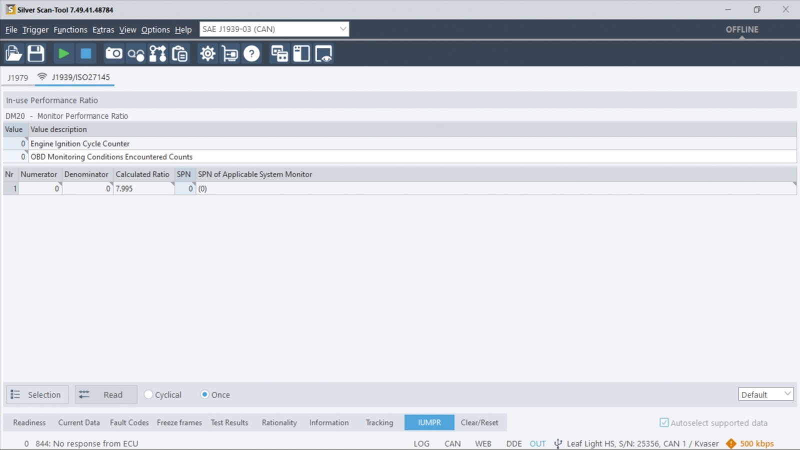
To measure the frequency of monitoring, an in-use monitor performance ratio is used. It defines the operational frequency of several monitoring strategies relative to specific drive cycle conditions.
It can be defined as the “Number of monitoring events/Number of driving events”, It means the ratio of the number of times the conditions have existed under which a monitor should detect a malfunction to the number of driving cycles applicable to that monitor. Each component such as fuel system, cooling system, exhaust gas sensors, other emission control system monitoring, etc. requires its own ratio. This IUMPR is measured by incrementing a counter when the monitoring conditions operate on-road and also tracking when the vehicle driving cycle meets specified milestones.
To view IUMPR value you can use diagnostics tools like Silver Scan tool or DiagRA D. Each software comes with all the functions you need to carry out complete OBD diagnostics and archive them in a legally secure manner. Measured values are displayed numerically and graphically. The below figure shows the IUMPR measured in the silver scan tool.
Deprecated: Creation of dynamic property Item::$renderers_validated is deprecated in /home/u723625802/domains/skillicon.in/public_html/blogs/inc/items/model/_item.class.php on line 11107
Deprecated: Creation of dynamic property Item::$pages is deprecated in /home/u723625802/domains/skillicon.in/public_html/blogs/inc/items/model/_item.class.php on line 2412
Deprecated: strtr(): Passing null to parameter #1 ($string) of type string is deprecated in /home/u723625802/domains/skillicon.in/public_html/blogs/inc/_core/_misc.funcs.php on line 766
Deprecated: strtr(): Passing null to parameter #1 ($string) of type string is deprecated in /home/u723625802/domains/skillicon.in/public_html/blogs/inc/_core/_misc.funcs.php on line 766
Deprecated: strtr(): Passing null to parameter #1 ($string) of type string is deprecated in /home/u723625802/domains/skillicon.in/public_html/blogs/inc/_core/_misc.funcs.php on line 766
Deprecated: strtr(): Passing null to parameter #1 ($string) of type string is deprecated in /home/u723625802/domains/skillicon.in/public_html/blogs/inc/_core/_misc.funcs.php on line 766
Deprecated: Creation of dynamic property ItemSettings::$count_col_key_names is deprecated in /home/u723625802/domains/skillicon.in/public_html/blogs/inc/settings/model/_abstractsettings.class.php on line 121
CAN stands for Controller Area Network, it is defined in ISO-Standard 11898, often used in automotive environments. It acts as a nervous system inside the vehicle for enabling communication between all ECUs(Electronic Control Unit) with each other applications.
ECUs are interconnected with the CAN bus, information sensed by one ECU will be shared with other ECUs e.g., engine control module, brake control module, transmission control module, Airbag, audio system, etc. A modern car has more than 70 ECUs.
CAN bus is a Multiplexed network, all ECUs(nodes) are connected to physically conventional two wire bus. The wire is a twisted pair with a 120 Ω Terminating Resistors to avoid the reflections. This bus uses differential wired AND signals, CAN high (CANH) and CAN low (CANL), the signal will be in dominant state when CANH > CANL. A Logical 1 is said to be dominant state, while a Logical 0 bit is recessive state. ECU will broadcast the message, all other ECUs will receive the message on CAN network and each ECU will check the data and decide whether to receive or ignore it.


Communication over the CAN bus is done through CAN frames. Standard CAN frame consists of 11 bits identifier (CAN 2.0A), which is used by most of the vehicles. The extended CAN frame consists of 29-bit identifier frame (CAN 2.0B).
Structure of CAN frame.
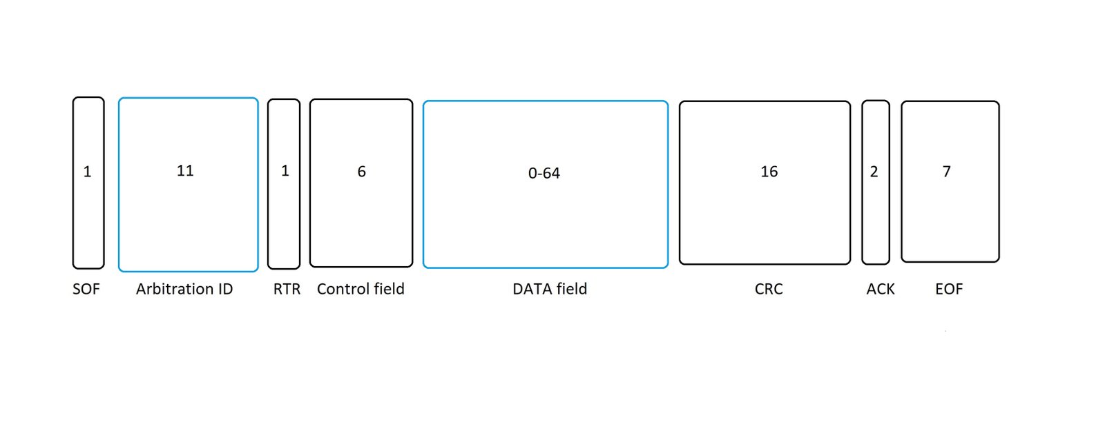
SOF (Start of frame): Identifies start of frame.
Arbitration field: All node consists of arbitration ID which determines the priority of the messages on the bus. If multiple nodes try to transmit a message onto the CAN bus at the same time, the nodes with high priority (lowest arbitration ID) automatically gets bus access. Nodes with a lower priority must wait until the bus becomes free before trying to transmit again. The waiting devices wait until the end of the frame section is detected.
RTR: The Remote Transmission Request indicates whether a node sends data or requests dedicated data from another node.
Control field: To distinguish standard and extended frame formats, the IDE-bit (identifier extension bit) is used. A reserved bit intended for future extensions follows. The last 4 bits (DLC) identify the number of bytes included in the data field.
Data filed: The data field consists of actual data being transmitted. Its length can range from 0 to 8 byte.
CRC field: Contains a check sum that is used to identify bit errors.
ACK(Acknowledgment) field: The transmitter node sends a recessive ACK bit and every receiver node that identifies the message checks if the received message is accurate if yes it overwrites ACK bit with a dominant bit. If the receiving node does not change this bit, it means that the message may have an error and will be discarded.
EOF (End of Frame): Identifies the end of message.
To analyze CAN signals you can use CANEasy. CanEasy is a Windows based analysis and testing environment for CAN (FD), LIN and Automotive Ethernet. It can be used directly without any complex configuration or programming. CanEasy automatically simulates the behavior of all ECUs based on the communication matrix. The user can directly access all signals of the database, via generated panels and editors. Due to the automatically generated panels, the high level of automation and programmability, CanEasy can be used very quickly and flexibly. It saves effort, time and costs compared to common development tools.

Deprecated: Creation of dynamic property Item::$renderers_validated is deprecated in /home/u723625802/domains/skillicon.in/public_html/blogs/inc/items/model/_item.class.php on line 11107
Deprecated: Creation of dynamic property Item::$pages is deprecated in /home/u723625802/domains/skillicon.in/public_html/blogs/inc/items/model/_item.class.php on line 2412
Deprecated: Creation of dynamic property ItemSettings::$count_col_key_names is deprecated in /home/u723625802/domains/skillicon.in/public_html/blogs/inc/settings/model/_abstractsettings.class.php on line 121

With BSVI (Bharath Stage 6 – BS6), On-Board Diagnostics (OBD) has become popular among the masses. More and more people have started to recognize and understand the role of electronics in automobiles.
Vehicle diagnostics opens up a plethora of applications in automotive engineering and forms the future of Automotive – Internet of Things “IoT” (also called as Internet of Vehicles “IoV”). As the name suggests diagnostics is about finding the faults in the system, but it does not stop there. With diagnostics, we can read not only fault codes but also other data pertaining to the operation of automobiles. We can also instruct the automobile to perform particular actions.
Deprecated: Creation of dynamic property Item::$renderers_validated is deprecated in /home/u723625802/domains/skillicon.in/public_html/blogs/inc/items/model/_item.class.php on line 11107
Deprecated: Creation of dynamic property Item::$pages is deprecated in /home/u723625802/domains/skillicon.in/public_html/blogs/inc/items/model/_item.class.php on line 2412
Deprecated: Creation of dynamic property ItemSettings::$count_col_key_names is deprecated in /home/u723625802/domains/skillicon.in/public_html/blogs/inc/settings/model/_abstractsettings.class.php on line 121

1.Accuracy of OBD standards: Silver Scan-Tool (SST) is used by authorities themselves for homologation and certification. Using SST you can make sure that there are no unfulfilled OBD conditions before going for certification.
2. One tool for all OBD standards: There is no need to invest in multiple tools for different OBS protocols/standards. SST supports different protocols and standards:
Deprecated: Creation of dynamic property Item::$renderers_validated is deprecated in /home/u723625802/domains/skillicon.in/public_html/blogs/inc/items/model/_item.class.php on line 11107
Deprecated: Creation of dynamic property Item::$pages is deprecated in /home/u723625802/domains/skillicon.in/public_html/blogs/inc/items/model/_item.class.php on line 2412
Deprecated: Creation of dynamic property ItemSettings::$count_col_key_names is deprecated in /home/u723625802/domains/skillicon.in/public_html/blogs/inc/settings/model/_abstractsettings.class.php on line 121
The market for Electric Vehicles is on the rise and development is heading at a fast pace. What about diagnostics on EVs?
This article speaks about different diagnostic standards for different kinds of vehicles and throws light on diagnostics for EVs.
There are different protocols/standards in vehicle diagnostics. The main ones accepted and used worldwide are:

Deprecated: Creation of dynamic property Item::$renderers_validated is deprecated in /home/u723625802/domains/skillicon.in/public_html/blogs/inc/items/model/_item.class.php on line 11107
Deprecated: Creation of dynamic property Item::$pages is deprecated in /home/u723625802/domains/skillicon.in/public_html/blogs/inc/items/model/_item.class.php on line 2412
Deprecated: Creation of dynamic property ItemSettings::$count_col_key_names is deprecated in /home/u723625802/domains/skillicon.in/public_html/blogs/inc/settings/model/_abstractsettings.class.php on line 121

Most of the time we associate Vehicle Diagnostics to OBD-II which is a certification requirement and the possibilities are extremely limited. But Vehicle Diagnostics opens up an entire lot of automotive testing possibilities. The following are the uses of Vehicle Diagnostics: